Riyadh Metro track construction
Jim Douglas, BDM Engineering, Hexagon

THIS article is a personal report on some of the aspects of both the design and build and later the maintenance of track on lines 4, 5 and 6 of the Riyadh Metro.
It is made with a special focus on positioning of the alignment and later the measurement of the tracks’ geometrical quality, which was but a small portion of the overall challenge for the consortia engaged for the systemwide works of the project.
Riyadh Metro is a high-performance driverless system with a capacity to handle 10,000 people per hour per direction using headways of approximately 100 seconds.
Its track and systems handle gradients of up to 6% and climate conditions from -5 ° to +50° with wind-blown sand. Power supply is provided by an inverted 750VDC conductor rail. Maximum speed is designed to be 80km/h.
Riyadh Metro is initially formed of six lines, designed and built by three different consortia. Lines 4, 5 and 6 were built by the FAST consortium and to be operated and maintained by FLOW.
Alstom Transport is a member of both entities. Other members of FAST included FCC, Strukton, Samsung and Freyssinet. In FLOW, Hitachi is a major partner to Alstom.
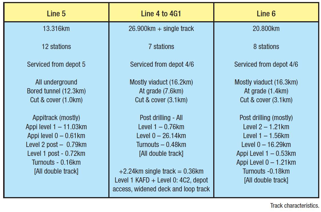
Track design
Track foundation is reinforced slab and runs on viaduct, at grade and in a large diameter tunnel. In order to accommodate the mechanical, electrical, power and drainage system-wide layout with appropriate gaps and openings, all the track slabs of approximately 5.5m in length and 2.5m wide were precisely defined for location and type in the detailed design. Slab (and its reinforcement) is superelevated for curves where required. This means track baseplates can always be directly fixed to the top of concrete.

Tolerances for concrete level were nominally +/-5 mm.
Design clearances between reinforcement bars location and fastening dowels (housing the screws inserted into the slab from the baseplate) were only around 20mm in plan in some places. This was the complete error budget for cage fabrication and placement and then baseplate insertion.
See Figure 1.
Baseplates and their fastenings are designed for three noise and vibration attenuation levels 0, 1 and 2 to manage the metro in sensitive locations. Dampening is mostly achieved by softer and thicker pads, increasing the height of the rail above the slab.
Level 2 (highest) attenuation requires the rails to ‘float’ whilst clamped in a Pandrol Vanguard fastening. Track installation on lines 4, 5 and 6 used three methodologies: Mechanised insertion of baseplates in ‘wet’ trackslab (Appitrack); ‘post-drilling’ in already paved trackslab; and classical ‘cast-in-situ ’ top-down with jigs and props supporting the rails and baseplates for the pour.
The classical methodology was primarily used for mainline turnouts and some very short plain line infills. Thousands of slabs and associated reinforcement cages were drawn in CAD for detailed design with many different slab types to accommodate different baseplates, superelevations and curvatures.
Slab setting out
Paver guidance used machine control with dual prism masts for position and alignment of the paver. Level sensors handled the machine pitch and crossfall. To handle the setting out of these designs FAST elected to use Leica Geosystems TS16 total stations operating with Captivate engineering applications software. This software can view, select and set out points and lines from CAD files whilst reporting offsets to the track alignments. This enabled working positions for the slab shutters to be established directly from the CAD models on site.
Furthermore, for all Appitrack zones and in locations where reinforcement bars had to be in close proximity to baseplate dowels, ‘as-laid’ checks were made by measuring the salient bars and computing their as-built positions with respect to the theoretical positions of the baseplate dowels in the slab.
With a library of cage designs and the dowel positions in the slab modelled for cant an Excel sheet could receive Captivate outputs and compute proximities.
Normally in 1-5 % of cases a re-adjustment of the as-laid cage position was required in order to avoid a dowel strike on the reinforcement, which for Appitrack baseplate insertion was critical to avoid. As part of the workflow on site a tag system was employed where coloured ribbons were attached to each cage ahead of the paver; orange – ready to check; green checked and ok; red – not ok, move; orange – ready to check again.
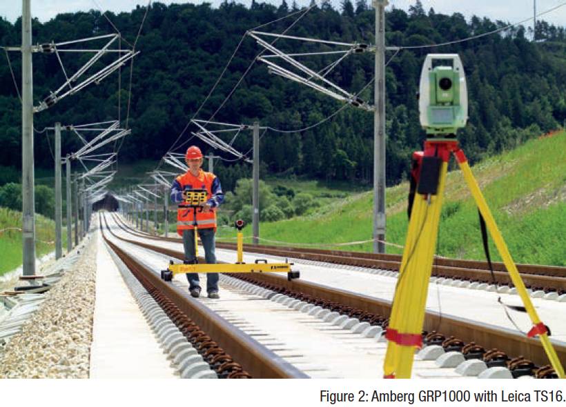
Paver guidance
Paver guidance used machine control with dual prism masts for position and alignment of the paver. Level sensors handled the machine pitch and crossfall. Guidance from two TS16 total stations (one for each mast) was enabled by a constellation of control prisms drilled into the floor, walls and, in tunnels, the roof of the civil infrastructure. On the viaduct the control prisms could only be installed on the piers to assure stability.
In the tunnels the space in front of the total station was extremely limited because both tracks were occupied by machinery during paving.In the tunnels the space in front of the total station in the direction of construction was extremely limited because both tracks were occupied by machinery during paving. This was because one track was used to construct the other.
When working on the first track in a particular location the second track used temporary track panels to enable concrete delivery for the paver via hoppers and an excavator (for shunting and placement in the paver). Once the first permanent track was built it could be used in the same way as the temporary track to construct the second.
Track positioning
For post-drilling zones, mostly on line 4 and line 6, and where noise and vibration levels were 0 and 1, paving was undertaken independently of the fastening installation and later on a rolling rig was mounted on the rails for precise drilling through the holes in the baseplates placed accurately on the slab. This meant that permanent track panels (rails with fastenings and baseplates but temporarily without dowels) were laid to a stenciled track centreline and then finely adjusted insitu before the drilling.
For the adjustment, Amberg GRP1000 trolleys connected to Leica TS16s were used. The Pandrol baseplates contain horizontal and vertical adjustment characteristics (asymmetrical bolts, varying lateral insulator and vertical shim/pad thicknesses) but at this stage the horizontal position was achieved by a manual slue and the vertical position by using vertical shims inserted to a thickness calculated from the measurement of the asbuilt slab height.
Level 2 installation (about 3% of the track) and check rail installation (another 4%) required a different approach for drilling. For level 2 the rails float in the fastenings (there is space underneath the rail foot to the bump pad as per Figure 1).
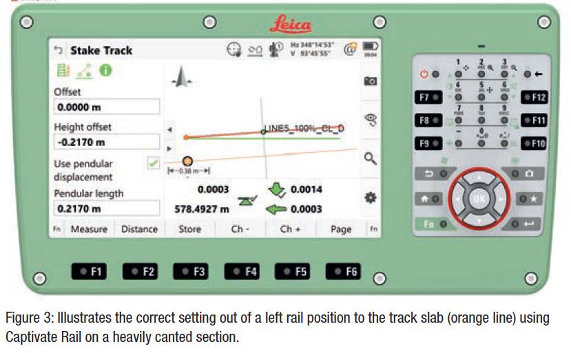
Therefore, there were no track panels laid to the slab as the arrangement is too delicate. Instead holes for the dowels were marked and drilled ahead of the baseplates being laid out and fixed to the slab without rails. Markings on the slab, which are 200-250mm below top of rail level, need to account for the effect of design cant on position.
On canted sections the centreline is shifted to a different position dependent upon the depth below the rails and the amount of cant.On canted sections the centreline is shifted to a different position dependent upon the depth below the rails and the amount of cant. One of the most useful features of the Captivate Rail solution onboard the Leica total stations is the ability to automatically calculate the precise shifts to the setting out using a pendular function which swings the trackform position with the superelevation.
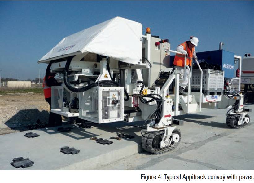
Mechanised baseplate insertion in wet concrete involves utilisation of an Appitrack machine in convoy with a paver (see Figure 3). Guidance for the paver is moved to the front of the convoy and guidance for the Appitrack machine to the back. Convoy speed was about 1m a minute. Appitrack has an insertion module or arm (two generations of Appitrack machine worked on Riyadh Metro) which shifts and articulates independently of the vehicle which moves forward on caterpillars.
The vehicle moves approximately to the next position of insertion and then the module or arm places the baseplate in the concrete to +/-3mm of the design position. The design depth of the baseplate in the concrete accommodates the worst cases of low slab + high baseplate and high slab + low baseplate.
Post convoy, for the Appitrack sections on line 5 and 6, a precise ‘shim plan’ was calculated by making an observation of each and every baseplate in its cast-in position. Using a special prism device fabricated to mimic the rail in-situ with a nominal set of lateral insulators and vertical shims (which placed the assembly in the middle of the +/-5mm adjustment range) measurements were undertaken by TS16 using Captivate Rail software for zones of baseplates that were alpha-numerically labelled on site so as to clearly link the location of the shimming for the track construction teams without survey equipment.
A major contributor to this achievement was the employment of methodology to eliminate the small disagreements of a few mm between each set of observations.Although highly intensive (there were 200 observations required for 70m of track) this pre-rail installation survey proved to be the last time topographic positioning methods were needed for these sections. This made a significant contribution to a programme for rapid delivery of finally adjusted track. A major contributor to this achievement was the employment of methodology to eliminate the small disagreements of a few millimetres between each set of observations.
These disagreements, whilst normally tolerable in civil engineering, are not acceptable in slab track construction where positional agreement from one baseplate to the next (700mm away) needs to be approaching sub-millimetre in line and level for the smoothest of alignments. This smoothness was therefore achieved by new observations adopting wholly the values of previous observations in an overlap zone and then smoothing out this compensation over a length of track that introduced an insignificant rate of change for the railway.
For the mainline turnouts mounted on concrete sleepers, classic cast in-situ methods were used which were relatively slow as compared to the paving sections but justified by the positional criticality when installing expensive switches and crossings (S&C) units in concrete instead of on ballast.
All mainline turnouts used complex (non-linear) gauge widening to assist safe wheel entry to the switch. Interestingly this meant that neither the running edge nor the back edge of the rail could not be used as a surveyors rail reference on the switch.
Instead a special manufacturers mark (indicating the nominal back edge as if there is no widening) was referenced.
Final track adjustment
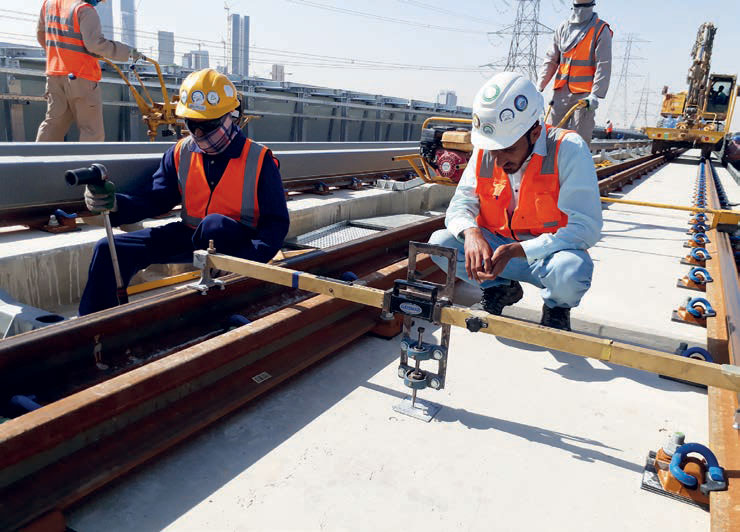
Figure 5 : Final track adjustment by track gauge with pointer.
When using topographic methods for track positioning it is usual to select a control rail which defines the alignment and a gauge rail which is, as the name suggests, positioned by a gauge measurement from the control rail.Track tolerances were nominally +/3mm for absolute position and 2mm/10m horizontal and 2mm/3m vertical for rate of change, cant +/-2mm and gauge +1/-2mm.
With baseplates individually installed to slab rather than via a sleeper the main challenge in terms of geometry was controlling gauge.
When using topographic methods for track positioning it is usual to select a control rail which defines the alignment and a gauge rail which is, as the name suggests, positioned by a gauge measurement from the control rail.
This achieves the desirable effect of avoiding the compounding of small errors in alignment with small errors in gauge.
In general the control rail for final adjustment was selected to be as follows, on canted zones – the low rail (also closest to the check rail); on uncanted zones – the rail closest to the conductor rail.
This was to avoid moving this rail to achieve gauge, which would then disturb the gap precisely set for the train collector shoe contact with the conductor rail.
Final track adjustment on the level 0 and 1 sections was undertaken using Amberg GRP1000 on curved and canted sections. On sections of straight without cant (70% of line 6) it was possible to formulate a final adjustment using a track gauge with a pointer. See Figure 5. A punched centre plate was referenced by the pointer and the gauge and cant checked and adjusted when necessary. All adjustments were effected by modifying the fastening settings and shims from those used for the initial track positioning to the slab. All level 2 sections were adjusted by GRP1000.
On Appitrack sections it was evaluated that cant checks (no cant adjustment was found to be needed after the shim plan implentation) and refinement of gauge would be sufficient to place the track in its final state without any further alignment adjustment using topographic methods such as GRP1000. Therefore, a team was deployed to check (every 5m) and, where necessary, adjust the track with a standard track gauge. The logistics of carrying just a few extra shims and making the adjustments straightaway was sufficient because in general one adjusted baseplate would effectively exchange its shims with another.
This rapid transformation to final adjustment (as compared to the drilling sections) and without further topographic surveying was vindication for the initially intensive shim plan method.
Viaduct challenges
Critically it was evident from the monitoring that the heave did not undermine the rates of change tolerance required for the vertical alignment. During preparations for the paving operations on viaduct highly precise monitoring was employed. This mostly used prisms mounted to bolts drilled into the structure, observed by a TS16 and compared to similarly installed prisms installed on buildings adjacent to the viaduct. Using a pattern of very similar instrument positions for each round of monitoring and a least squares adjustment the results could be shown to be approaching submillimetre levels.
The monitoring was undertaken to measure the behavior of the viaducts under load from the aggregation of machinery and concrete as the track slabs were installed, first on one track and then the other. These loading behaviors were then accounted for in the positioning of the trackslab using a construction vertical alignment. However, it also became apparent that alongside the loading affect was a thermal effect observable both between night and day (and between the seasons) which led to the expansion of the viaduct in the sun and a heave affect of a few millimetres.
Subsequently it was agreed that the absolute vertical tolerance on viaducts would be difficult to achieve and therefore subject to a relaxation. Critically it was evident from the monitoring that the heave did not undermine the rates of change tolerance required for the vertical alignment.
Track geometry reports
The TSM has proven extremely useful not just for track geometry assessment but also for monitoring the safety critical check rail and conductor rail gaps.The final stage for acceptance of the as-built track alignment was the recording of a track geometry report of high frequency measurements (point on each rail every 250mm) independent of the surveying used for the positioning. This report was based upon the analysis of trolley versine measurements that were to confirm or otherwise the smoothness of the alignment (a corollary of rate of change tolerances) using mean to peak analysis.
Mean to peak compares the individual versine value (peak) at a particular point with the average versine value (mean) for all of the points within the wavelength being considered (10m for horizontal in this case). Typically a trolley system measures sub-millimetre versines over a real base about 1-1.5m long using very sensitive rail touch points at the back and front wheels and in the middle of its frame. The system works very effectively on continuously welded rail with a polished running edge (contact point around 14mm beneath the top of rail).
However, if there is construction debris/ dust some false readings are possible. The policy with trolley runs was to identify (the relatively few) sections where unacceptable peaks were recorded, clean the rail again and re-run the trolley. If for both runs the unacceptable peak appeared in the same location the section of track would be unfastened and re-adjusted by survey methods before again being measured by the versine trolley system.
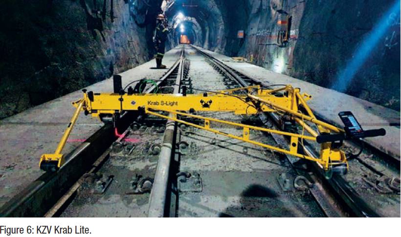
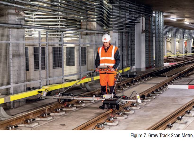
KZV’s Krab Lite (Figure 6) was used for the final design and build reports. In the operation and maintenance phase a Graw Track Scan Metro (TSM) (Figure 7) is being used. It is with this tool and its measurements that the analysis that follows is based. The TSM has proven extremely useful not just for track geometry assessment but also for monitoring the safety critical check rail and conductor rail gaps. It also provides rail wear assessments to enable the planning of targeted grinding campaigns.
Wider analysis of the track geometry quality beyond project tolerance
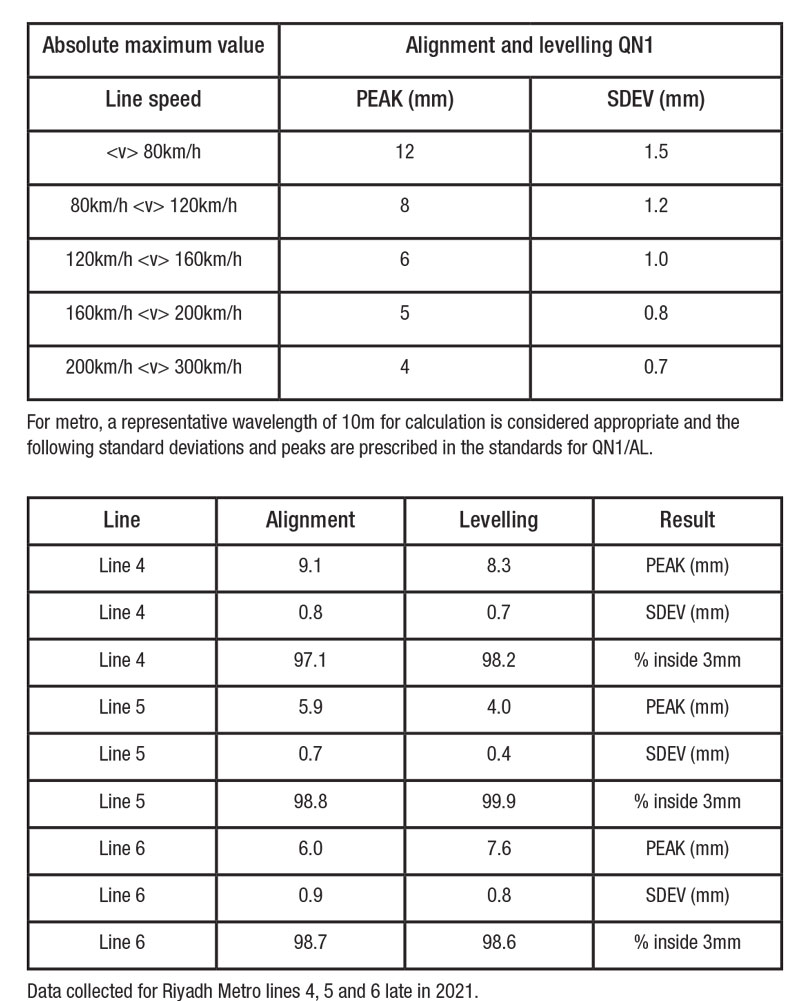
In all cases, for all lines, all of the slab track very comfortably falls within the QN1 standard for linespeed to 80km/h.
European Standard series EN 13848: Railway applications – Track – Track geometry quality [3] and UIC standard 518 can be treated as basic norms correlating track geometry reported by peaks and standard deviations to line speed. The series EN 13848 covers the wide-ranging problems of classifications irregularities, their recording, measurements and used measuring devices.
Geometric quality levels defines the quality levels of the track geometry. They are called alert limit (AL), intervention limit (IL) and immediate action limit (IAL). UIC standard 518 sets also three quality levels with similar meaning of AL, IL and IAL but with different names: QN1, QN2 and QN3 respectively.
The definitions are as follows:
- QN1 quality level (AL – alert limit): This refers to the value which necessitates monitoring or taking maintenance actions as part of regularly-planned maintenance operations.
- QN2 quality level (IL – intervention limit): This refers to the value that requires short term maintenance action.
- QN3 quality level (IAL – immediate action limit): This refers to the value above which is no longer desirable to maintain the scheduled traffic speed.
Analysis
Overall Riyadh Metro lines 4, 5 and 6 produced evidence to vindicate use of rails-off/bottom-up methods (as compared to classic top down) in terms of quality, justifying these more flexible methods for track construction.In all cases, for all lines, all of the slab track very comfortably falls within the QN1 standard for line-speed to 80km/h. In general track quality is similarly high for lines 4, 5 and 6. Line 5, completely protected from the elements, and not on viaduct, exhibits a slightly higher quality of alignment and leveling than line 4 and line 6.
This is graphically illustrated by the plotting of the mean to peak results for a length of track on line 5 and line 4 with similar straight geometry.
Clearly the worst peaks of line 4 sit above those of line 5 (although only 2.8% of the 4,000 data points for line 4 sit above the 3mm level).
Conclusion
Perhaps understandably the line without viaduct has lower peaks than those lines with. But in general the results were of the same order for all lines. Appitrack is a bottom-up method. Whereas post-drilling for noise and vibration levels 0 and 1 is effectively top-down with rail adjusted before drilling with adjusted baseplates in-situ.
Line 5 did not use labour intensive topographic methods after the highly focused shim-plan stage, yet the track quality was not adversely affected at all. Overall, Riyadh Metro lines 4, 5 and 6 produced evidence to vindicate use of rails-off/bottom-up methods (as compared to classic top down) in terms of quality, justifying these more flexible methods for track construction.
Jim Douglas, BDM Engineering, Hexagaon
Jim Douglas is a former construction survey manager and track maintenance manager for Riyadh Metro.