Marston Box slide
Nigel Evans MCInstCES AssocRICS AMICE, Survey Manager, Sublot 7 | Balfour Beatty VINCI | HS2
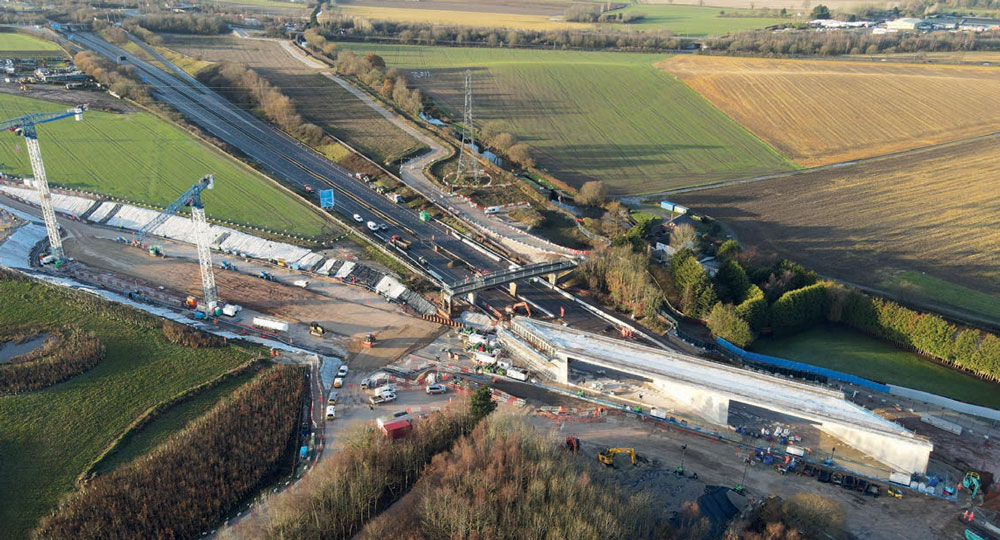
THE Marston Box is a bridge structure designed to carry high-speed trains across the M42 motorway, in North Warwickshire and is part of the Balfour Beatty Vinci contract for HS2.
Specifically, it is located within Sublot 7 of the contract, which runs from Faraday Avenue near Coleshill to Hints Lane near Tamworth, a distance of 13km.
The length of the box is 86m and width is 20m with a gross weight being 12,600t.
The box was constructed on a guide raft which extended 80m in front of it and allowed the initial slide to be guided, with the final part of slide taking place over impermeable and compacted material.
The purpose of this ground improvement was to have a compacted soil which will prevent any settlement of the box, and impermeable, to make sure that the bentonite, used as the lubricant agent between the box structure and the raft, does not penetrate the ground once being injected during the slide operation.
Jacks illustrating the strands located at the rear of the box structure.
The surface of the guide raft had to be completely smooth with a polished finish, which was achieved using a power float.
The level tolerance of the guide raft was 7mm, and a final as-built survey was conducted on the raft, at 1.5m intervals, with the results being sent to Freyssinet, for approval – the specialist civil and structural engineering company responsible for designing the sliding mechanism.
The total length of the slide was 162.8m and was undertaken over the 2022 Christmas period, with the M42 being closed in both directions to allow it to be excavated to accommodate the new structure.
Freyssinet was awarded the subcontract for the actual slide operations which consisted of the following procedure:
- Nine passive deviators were installed at the front of the box (north side) and once the position was approved concrete was poured and the installation was complete.
- Nine active deviators were installed at the rear of the box (south side). These were positioned on the guide raft in advance of the strand installations, but without any reinforcement support. The reinforcement of the push slab was installed after the strand installations, around the active deviators. The active deviators themselves were then cast into the push slab, using steel plates.
- Nine tension cables were installed between the nine passive deviators and the nine active deviators. (Each cable was made up of 52 strands).
- Nine jacks were installed once the push slab had been constructed. The strands were inserted into each of the jacks in a numerical sequence ensuring no crossovers, until the whole of the cable of 52 strands had been inserted.
- To reduce friction, bentonite was injected to obtain a thin layer under the whole surface of the box, between the box itself and the guide raft, sprayed on the rest of the raft, and on the made-up ground. Bentonite was injected when deemed necessary, judging on the friction by monitoring the jack pressure.
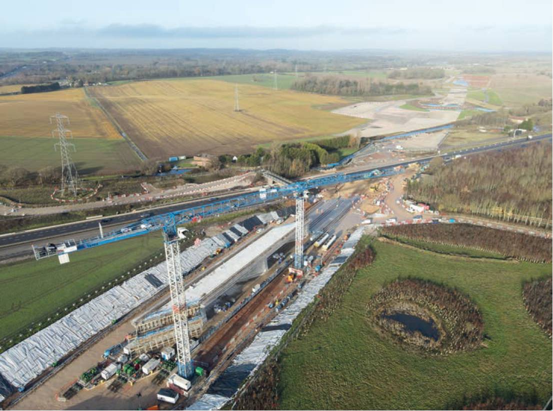
Marston Box pre-slide position.
Pre-slide survey works
Before any construction activities commenced the survey department started to install a secondary survey control network for the whole of the sublot. This secondary survey control consisted of a 1m x 1m x 1m excavated hole, filled with concrete and a FENO survey marker placed into it.
The secondary control network was tied back to the primary control stations, which had already been established prior to BBV taking the contract. From this secondary control, a tertiary control network was established for this construction of the structures, and as part of this tertiary control network, the survey control for the Marston Box construction was established.
The determination of the values for each of the control pillars was conducted through traversing, with observations taken to all other visible pillars within the network.
The control for the box consisted of five pillars constructed around the periphery of the box, close enough to be used during construction, but far enough away as not to be damaged by any site activities.
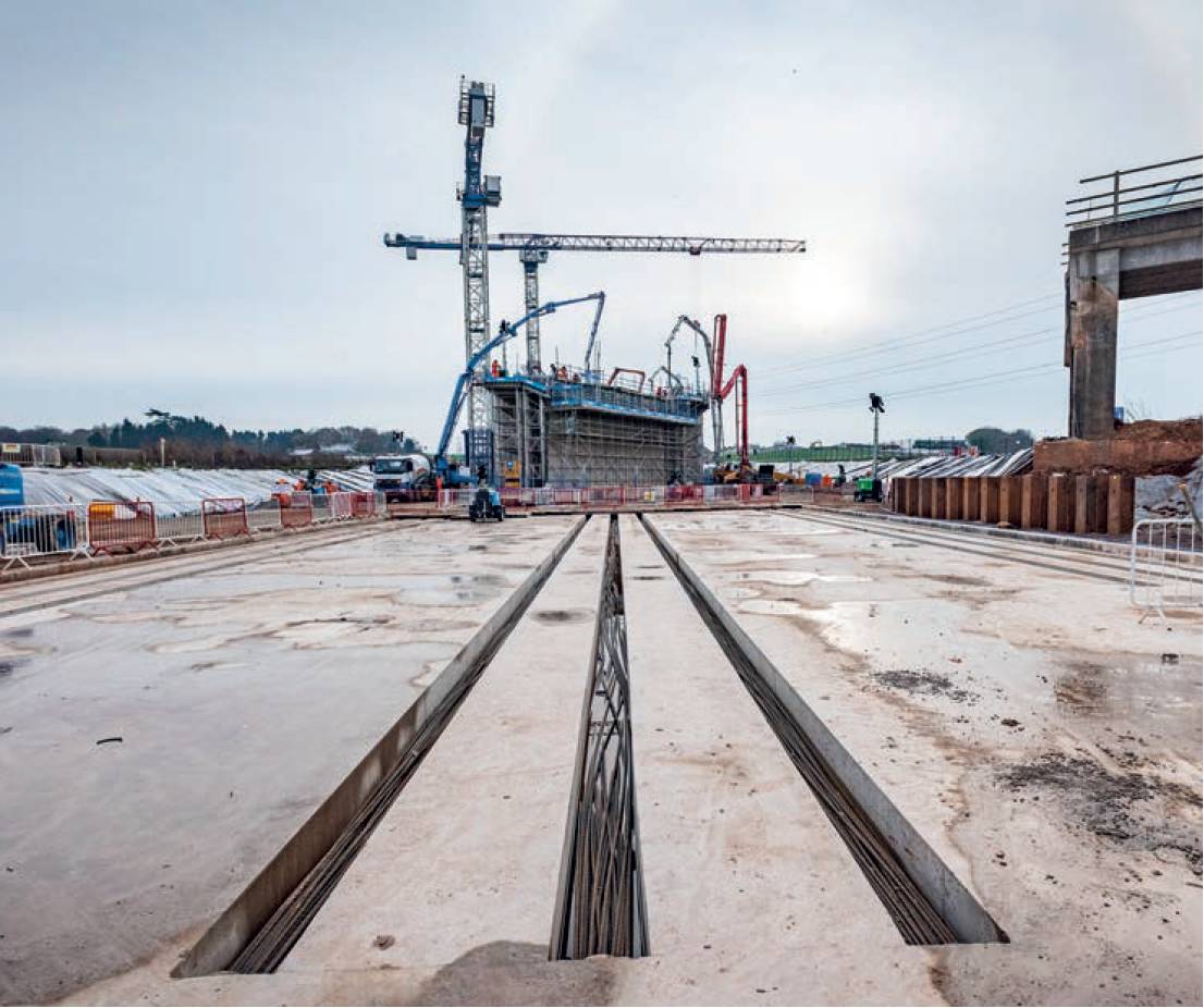
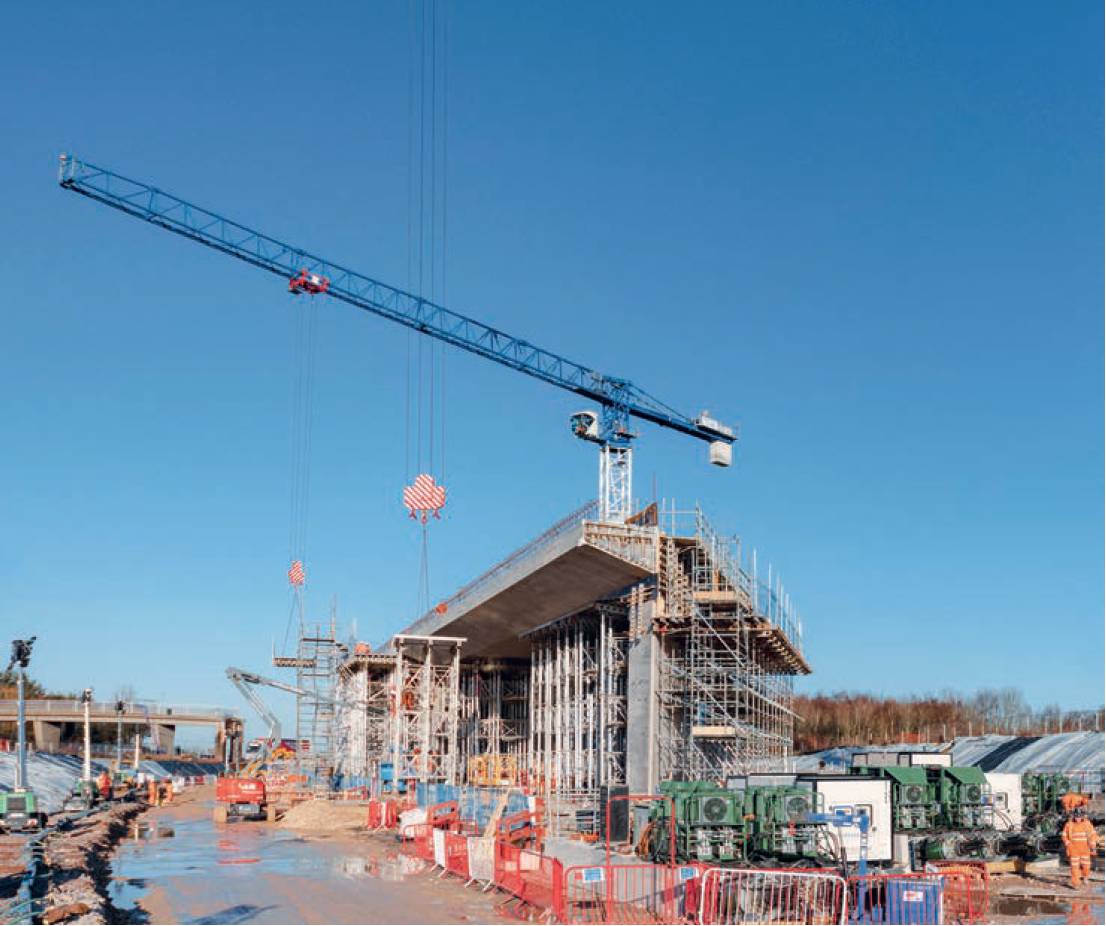
Box structure and the guide raft.
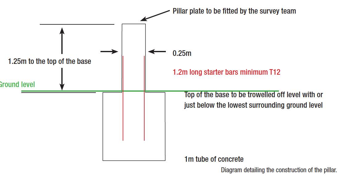
The construction of the pillars starts off similar to the construction for the secondary survey control.
The difference being, rebar is placed into the concrete base, a pipe is placed over it, 1.25m in height, and then filled with concrete.
Once the concrete is filled to the top of the pipe a pillar plate is placed into it. Using this system for the structures removes any cantering errors in optical plummets.
A levelling brass domed nail was also placed into the base of the wet concrete so an accurate elevation could be established at each one.
The determination of the values for each of the control pillars was conducted through traversing, with observations taken to all other visible pillars within the network.
The pillars were connected to the secondary control network by traversing, using a GeoMax Zoom 95 total station, onto two baselines, one to the north and the second to the south.
The elevations of the brass levelling bolts located on the base of each pillar were observed by connecting it to the secondary control network, using three already established benchmarks and using the double run method.

The levelling observations were carried out using a Leica LS15 and an invar staff. Also, during the levelling, observations were made to the pillar plates, to a part of the plate which had been scribed, so that any target/instrument heights will be measured from the same point. All the observations, both traversing and levelling, were processed using Starnet software. These pillars were then used for construction of the box and the guide raft. We undertook a six-monthly check on this control, as part of our QA policy and ensure that the control had not sustained any movement.
Monitoring discussions and methodology
In June 2022, discussions commenced between BBV, and all the other subcontractors who would be part of the construction of the Marston Box. The main subcontractor involved in the slide itself was Freyssinet. The initial discussions which took place between BBV Survey and Freyssinet to find out the requirements from survey for the slide itself.
This would entail simultaneous readings taking place from two surveyors, one taking observations at the front, and the other taking observations at the rear.
The slide would have to be continuously monitored over the required period and information passed on to Freyssinet as to changes in horizontal and vertical displacement. This information would have to be communicated to Freyssinet immediately, so that adjustment could be made to the rams to bring the structure back online.
Although the construction tolerance was +/- 50mm, we were asked to guarantee our readings to +/- 5mm, as the trigger values for the slide in horizontal and vertical displacement had already been set at +/- 10mm.
The guarantee of the observations was going to be extremely tight, but we felt that it was achievable. We were also given the responsibility of informing Freyssinet when the structure was at the correct, end position on the HS2 alignment.
We decided to come up with a method of monitoring, where prisms and reflective targets would be mounted at the front and rear of the box structure, and continually surveyed against an alignment which would provide us with information to whether it was moving to the left, right up or down.
The total number of targets mounted on the structure was seven at the front, and seven at the rear.
This would entail simultaneous readings taking place from two surveyors, one taking observations at the front, and the other taking observations at the rear.
As these observations were being compared to an alignment, we could also calculate a chainage, which meant we were able to give Freyssinet the distance they had travelled between observations and the distance remaining to be slid.
This would also give both BBV and Freyssinet an idea of how much the structure would be moving in any given hour.
The anticipate distance was approximately 4m per hour on the guide raft and 2m per hour when it slid over the made-up compacted material.
As-built survey and preparation works
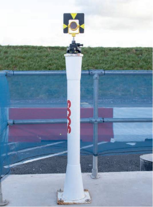
Pre-made steel pillar.
Before any other works were to be undertaken by the surveyors, we had to ensure that the pre-slide position of the box and the alignment was correct and was not going to impact its final position.
An as-built survey was undertaken of the box structure and compared to the design. The box itself conformed to all the tolerances as stipulated in the inspection test plan (ITP), and when the as-build alignment bearing was calculated and compared to the design as-built bearing, we only found a difference of 0.5” between them.
This showed that we were not going to have any problem in the tolerance in the final position, caused by errors between the bearings.
Due to the accuracies, we were being asked to achieve by Freyssinet, we had concern about achieving them in the vertical.
Trig heighting is not the most accurate method of determining the elevation of an object and having undertaken some tests on-site conclude that accuracies started to be impacted at around 75m.
If we were to have two fixed pillars for monitoring the structure during the slide they would be too far away from the prisms and reflective targets to guarantee achieving the required accuracies.
Therefore, it was decided that the method we would adopt would be to follow the slide and resection off the control to calculate our position.
However, the only survey control at the time available, were the original five control pillars which had been used for the box construction. We realised that more control would be needed for the slide to enable us to monitor the box effectively.
The additional control was going to be temporary, so we took the decision to place 1m x 1m x 1m in an excavated hole and smooth it off and ensure it was level with the existing ground.
When the concrete had gone off, we used pre-made steel pillars which were drilled and bolted to the concrete. By using pillars for the work, it would remove any centring errors within the optical plummets.
Six additional control points were established around the area which would provide us with a robust reliable control network to carry out the required monitoring works.
The new control points were traversed from the five existing control points. These five control stations would be fixed within the network and all visible points were observed to from all occupied stations.
A levelling run was then undertaken, again fixing the five initial control stations, the plates of the steel pillars being marked so any targets heights would be measured form the levelled point. All observations were processed through Starnet to give us a tight network.
Once the observations had been processed, we undertook resections check surveys to make sure the results we were measuring were going to give us the accuracies we needed. Random setups were carried out and observations made to the control, making sure that different combinations of the control were used.
The results we were consistently achieving, (around 1mm in horizontal and vertical), assured us that the control we had in place was more than sufficient for the work to follow.
The next work we needed to do, was the installation of the prisms and the reflective targets. We had a small window to do this, once the last concrete had been poured to the deck, but before the removal of the scaffolding. The prisms were fixed to the walls of the box, by drilling and fixing with screws and reinforcing the fix by using a strong adhesive both within the drilled holes and behind the spigot.
It was critical that we did not lose any of the prisms during the slide operations. The reflective targets were attached to the upstand by using a strong adhesive.
Monitoring during slide operations
The slide operations were due to commence at midday on Christmas Eve. Possession of the M42 had already been obtained, and it would remain in place until 1 January 2023, a period of nearly nine days. The days leading up to the slide, all the survey equipment that would be utilised over the three-day period of the operation, was checked against our baseline to ensure all equipment was fit for use.
All checks were documented and were handed over to National Highways and HS2 as part of the QA process. The day before the operation was due to start, we took base readings against the prisms and reflective targets, from a variety of locations, so we could get a good average set of readings when compared against the design alignment. By doing this, we had a known position of the monitoring points against the design alignment, and their offsets.
Readings would be taken for every slide cycle, which would be an hour in duration, and four metres in distance. The change in the offset, both horizontal and vertical, would be conveyed to the Freyssinet project engineer. The slide operation would be a continuous operation, and therefore would run for 24 hours a day until final position was reached. The trigger values in both horizontal and vertical was +/- 10mm, which was well within the design final construction tolerance of +/- 50mm in both horizontal and vertical.
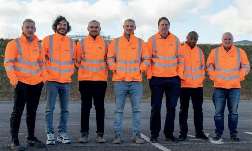
The survey team L-R: Callum Wale (junior engineering surveyor),Cem Kosem (engineering surveyor), Joshua Carter (engineering surveyor), Andrew Boyack TCInstCES (engineering surveyor), David Davis (senior engineering surveyor), Chuka Bosah MCInstCES (engineering surveyor) and Nigel Evans MCInstCES (survey manager
Although we experienced fluctuations in the readings, and on occasion reached trigger values, by the results being passed to the Freyssinet team quickly, adjustments could be made to the jacks to bring the structure back within acceptable tolerances.
When the structure was approaching the 30m limit to it’s final position.
We marked it by setting out a row of flags at the front and at the rear of the structure. This was purely the theoretical position for the Freyssinet team to have a visual reference, as to how far was left before operations would stop.
However, we had a more accurate method for this, as we had already calculated the chainage for each of the monitoring targets.
The final say to stopping the slide operations would fall squarely on the shoulders of the surveyors in the field.
This was achieved, with the final position being within the acceptable construction limits.
Conclusions
Being given the responsibility for the monitoring of this operation, caused me a few sleepless nights. This was the longest distance ever attempted for a box structure, and even though, with our many years’ of experience in construction, this was new to us all. The method of monitoring we adopted, may not be the most efficient, but it’s the method that we came up with, given the tight constraints we had to work to.
I’m sure this article will be read by surveyors who would have done it differently.
All I can say is, that it worked, it achieved what it was supposed to achieve, and as a team, we provided the right information, at the right time, to ensure a successful completion of the slide operation.
Nigel Evans MCInstCES AssocRICS AMICE, Survey Manager, Sublot 7 / Balfour Beatty VINCI / HS2 Area North IPT
nigel.evans@balfourbeattyvinci.com
Acknowledgments
I would like to thank the following people for help and support in putting this article together:
- Emmanuel Costes – project director Sublots 7 & 8 (Balfour Beatty Vinci)
- Sasan Ghavami – deputy project director Sublot 7 (Balfour Beatty Vinci)
- Caroline Warrington – senior project manager (HS2)
- Claire Beucherie – project manager Sublot 7.1 (Balfour Beatty Vinci)
- David Davis – senior engineering surveyor (Balfour Beatty Vinci)
- HS2 Ltd – aerial imagery