Underwater surveying with taut wires
Joel Mayer and Dr Dongfang Liang, Department of Engineering, University of Cambridge
FOR offshore surveying, a multitude of techniques already exist. These include long baseline acoustics, short baseline acoustics, photogrammetric metrology, INS metrology, digital and diver taut wire, the latter two being mostly superseded by the others. All of these techniques have been applied offshore and many of them are well established1, 2.
However, onshore surveying, which takes place in shallow waters close to shore or inland, involves some very different constraints we must consider.
These being smaller length scales, shorter time durations, lower budgets and lower visibility which make the aforementioned methods unsuitable for onshore diving contractors. For these reasons, a significant gap exists in onshore surveying capability where rudimentary methods are inappropriate and offshore methods cannot be used due to these constraints. Hence, the aim of this study is to devise a surveying method suitable to operate in these conditions and provide this novel capability.
The central component of our apparatus is a base station which operates like a total station.Considering constraints like cost and scale, we have decided to design and build an underwater metrology system for onshore use by divers without using acoustics for positioning3.
This is achieved by adapting not only existing offshore methods but also conventional land surveying methods for use underwater. The system uses the direction and extension of a wire to record positions.
However, it uses an acoustic modem for telemetry as the operating diver will have to hold the wire to the point being measured and so will usually be out of reach of the base station.
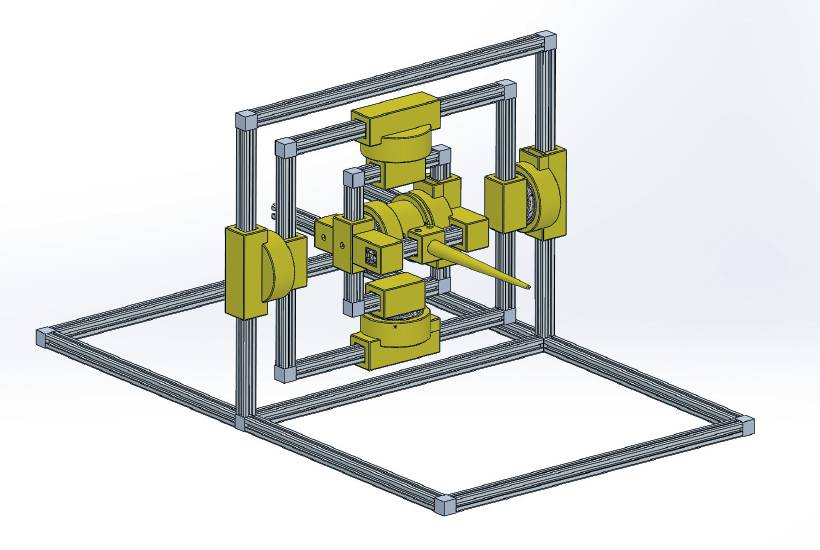
Figure 1: CAD for base station.
The final system can be applied to gather unknown dimensional data for already existing underwater structures so new parts can interface with them. This is a relatively common problem in the commercial diving industry, especially with historical underwater structures such as bridge foundations or sewer outlets that may be over a hundred years old. The system could also be used to measure deflections on newer underwater structures during inspection.
This will allow for less time to be spent taking measurements and labouring underwater, representing a large cost saving to onshore diving contractors. Considering constraints like cost and scale, we have decided to design and build an underwater metrology system for onshore use by divers without using acoustics for positioning.
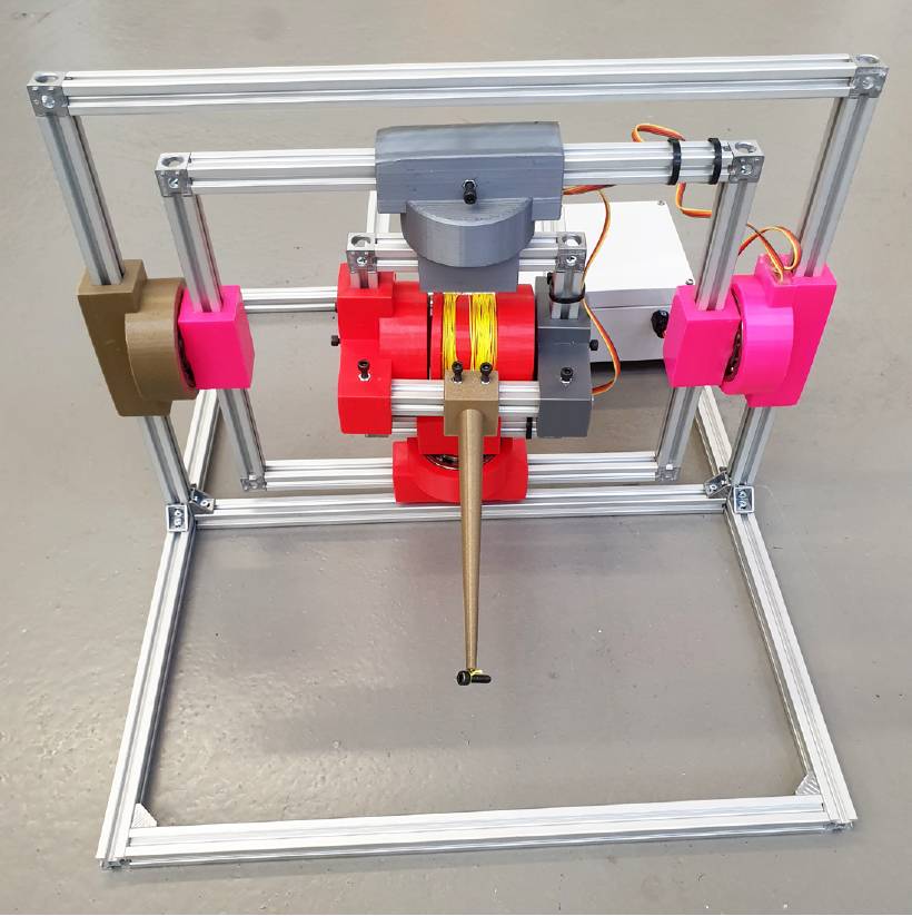
Figure 2: Fabricated base station.
Design of apparatus
The central component of our apparatus is a base station which operates like a total station, recording azimuth, elevation and extension of a wire that is kept taut by a coiled spring and touched to the target by the diver. The wire itself is neutrally buoyant in freshwater so forms a straight line when pulled taut.

Figure 3: Acoustic modem transmitter.
Transmitting chirps requires less power than quadrature amplitude modulation which other commercial acoustic modems typically use.The base station uses a Raspberry Pi for computation and storage of data and angles are measured with hall effect sensors.
The extension of the wire is derived from an angular measurement as well; the number of turns a drum containing the wire and rotated through.
A pressure sensor is incorporated into the design which we use to orientate our measured dataset.
Azimuth and elevation are measured via a gimbal system that contains the spool of wire. When the wire is extended, it runs through a stainless steel bushing of approximately equal diameter which acts as a guide.
This acts as a moment arm and aligns the gimbal with the direction of the wire.
The gimbal has bearings at each joint, half of which have hall effect sensors potted into them to record their angle. The gimbal is designed so buoyant force balances its weight when submerged.
Also included in our apparatus is an acoustic modem as the operator cannot physically operate our base station when extending the wire to the point of measurement. This is used to communicate when we wish to take a measurement.
An underwater trial was undertaken in an outdoor pool of approximately 2m depth in conditions analogous to those the apparatus would see commercial use in.We use a chirp modulation protocol to communicate from our transmitter to receiver with an up-chirp denoting a 1 and a down-chirp denoting a 0.
Chirps are already used in sonar and radar because of their high autocorrelation and temporal resolution making them easy to detect and less vulnerable to multipath effects.
In addition to this, transmitting chirps requires less power than quadrature amplitude modulation which other commercial acoustic modems typically use.
We demodulate our signal by taking the fast Fourier transform of our signal at intervals and looking for a moving peak. A matched filter would be more suitable but we are limited by our hardware in this instance.
Post-processing algorithm
Our post-processing algorithm must orientate each dataset relative to the others as they are each recorded from a different frame of reference. This isn’t usually done when land surveying as this is carried out on a plane with all base stations level.
With all datasets in the same frame of reference, we then have enough information from pressure readings to align to the global frame of reference and find the most likely locations of the measured points.
The program performs the following operations in sequence to accomplish this:
- A variation of Kabsch algorithm on the datasets from different base stations to place all points in the same frame of reference and deduce the known locations of the base stations as fixed points4.
- A least-squares regression to orientate the z axis of the data correctly and place all points at the correct depth.
- A least-squares adjustment to find the most likely location of each point using data from each base station dataset and generate error ellipsoids.
Underwater surveying example
Experimental setup
An underwater trial was undertaken in an outdoor pool of approximately 2m depth in conditions analogous to those the apparatus would see commercial use in. A grid of 30 target points was secured under the water and measured from six different base station locations. The grid was attached to the wall of the pool approximately vertical using adhesive.
Results
This is likely caused by the wire being obstructed during certain measurements as the error is only present for a small number of points and not systematic.
Running the data from our experiment through our algorithm yields the following results (see Figure 8).
The measured points are shown in purple, locations we measure pressure at shown in blue, and the centroid of the gimbal shown in green.
Our error ellipsoids for this experiment range from 0.3-3mm along their principal axis and are shown below scaled up by a factor of 10 (see Figure 9).
We see four of the larger error ellipsoids have a principal axis in approximately the same direction (and possibly a 5th smaller one).
This is likely caused by the wire being obstructed during certain measurements as the error is only present for a small number of points and not systematic (as would be the case if this was an issue with geometric stiffness).
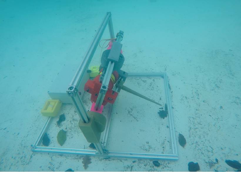
Figure 4: Base station underwater
All other error ellipsoids are of the order of magnitude we expect due to the high geometric stiffness we were able to achieve in this experiment. When comparing the reconstructed grid from our algorithm to our original grid, we have an absolute standard deviation of error of 1.1mm.
Error analysis
The assumption that the gimbal is completely free of resisting forces is incorrect; the cables for the hall effect sensors exert forces on the frame as they pass from one sub-frame to another.
We obviously have some sources of physical error here3 3, the most prevalent being the obstruction of the wire in some instances. Inconsistencies in the way the cable is wound on its spool, how accurately it is touched onto the point we want to measure and creep over time in the wire also cause some error.
In addition to this, the assumption that the gimbal is completely free of resisting forces is incorrect; the cables for the hall effect sensors exert forces on the frame as they pass from one sub-frame to another.
There are also some limitations in our algorithm, the first being that the geometry of our system is not accounted for in Kabsch algorithm. Kabsch algorithm minimises the square of the misalignment between datasets, not the normalised error of our measured angles if all datasets are aligned.
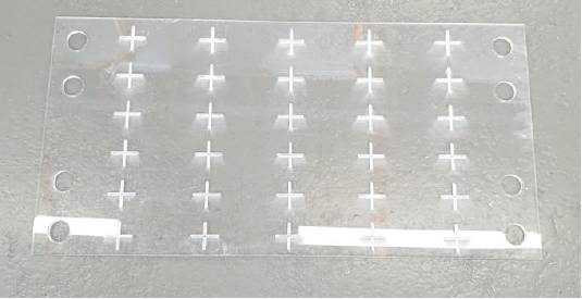
Figure 5: Grid of target points.
This means our base station locations, or fixed points, will not be placed accurately. A physically based algorithm that uses estimated standard deviation of error as stiffness for each measurement, aligns all datasets, and then relaxes to find an equilibrium solution would solve this. Another limitation is that our algorithm assumes all errors are distributed symmetrically.
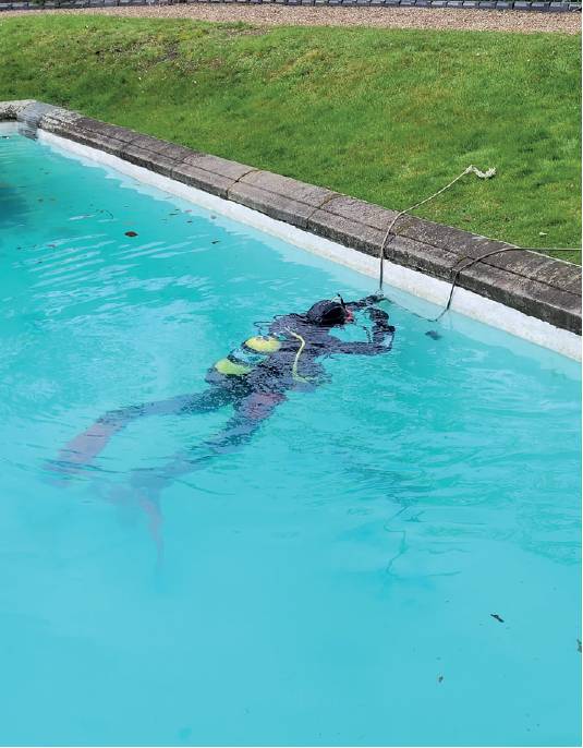
Figure 6: Taking measurements underwater
Conclusions
This provides a basis for underwater surveying in the onshore diving industry where factors such as small length scales, short project durations, lower budgets and low visibility make offshore methods unsuitable.
Using taut wire methods rather than acoustic methods for positioning, we can accurately determine locations by taking measurements from multiple base stations.
For our experiment, an absolute standard deviation of error of 1.1mm was achieved over 30 points from six base station locations each approximately 2m from the measured points.
This provides a basis for underwater surveying in the onshore diving industry where factors such as small length scales, short project durations, lower budgets and low visibility make offshore methods unsuitable3.
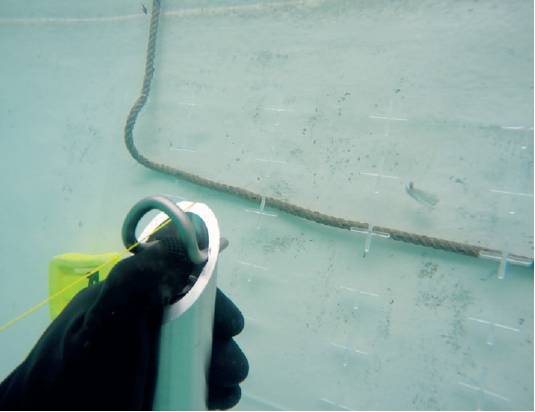
Figure 7: Aligning the acoustic modem transmitter and point to be measured.
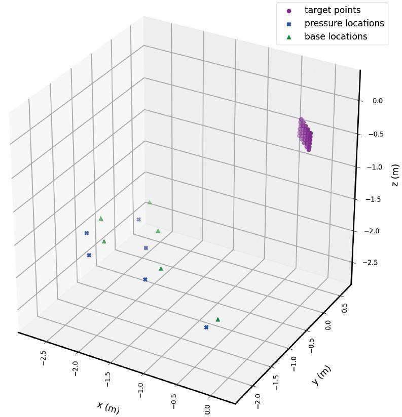
Figure 8: Below water results displayed by the algorithm.
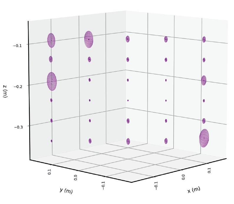
Figure 9: Error ellipsoids scaled up by a factor of 10.
Physical and analytical limitations reduce the accuracy of the system. The most notable of these sources of error is the use of Kabsch algorithm for point cloud localisation instead of an algorithm that minimises normalised sensor error, the assumption that all our errors are symmetrically distributed, obstruction of the wire, misalignment of the wire contact point, creep in the wire, spooling error and cable forces.
Joel Mayer and Dr Dongfang Liang, Department of Engineering, University of Cambridge
jm2255@cam.ac.uk dl359@cam.ac.uk
Acknowledgments
This work was funded by EPSRC grant numbers EP/I019308/1, EP/K000314/1, EP/L010917/1 and EP/N021614/1.
For the purpose of open access, the authors have applied a Creative Commons Attribution (CC BY) license to any Author Accepted Manuscript version arising. The underlying data can be accessed by emailing the authors.
---
1 Abimbola Bakare. Subsea Field Development: A Critical Review of Metrology Methods and Achievable Accuracies in Spool Tie-In Operations. [Master’s Thesis, Heriot-Watt University], 2013.
2 Arkadiusz Tomczak. Modern methods of underwater positioning applied in subsea mining. environmental engineering, mining and energy, 35(4):381–394, https://yadda.icm.edu.pl/yadda/element/bwmeta1.element.baztech-article-AGHM-0039-0047, 2011.
3 Joel Mayer. Underwater surveying using taut wires. [Master’s Thesis, University of Cambridge], 2022.
4 Berthold K. P. Horn. Closed-form solution of absolute orientation using unit quaternions. Journal of the Optical Society of America, 4(4):629–642, https://www.osapublishing.org/josaa/abstract.cfm?uri=josaa-4-4-629, 1987