Enhancing shallow subsurface surveys
Farough Rahimzadeh, Research Fellow in Geotechnical Engineering, and Jamie Vovrosh, Research Fellow in Cold Atom Sensing, Atom Interferometry Research Group, University of Birmingham
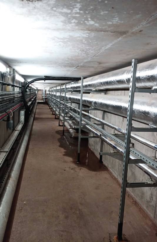
The inside of the service tunnel that was detected with the quantum technology based gravity gradient sensor.
GRAVITY sensing forms a useful tool for revealing subsurface features in a number of applications including civil engineering1, geology2, and archeology3.
One of the attractions of using gravity sensing in these applications is that intervening media does not attenuate gravity and meaning range is limited by the sensitivity of the sensor and not ground conditions.
However, despite the advantages and usefulness of gravity sensing, the current use of gravity sensors is limited due to traditional sensors’ sensitivity to vibration, tilt, and drift over time, which can severely limit the speed of surveys4, 5.
These drawbacks experienced by the current generation of gravity sensors limit their widespread use and commercial uptake.
The next generation of quantum technology-based sensors offer a potential solution to the issues, as well as for high quality data collected in less time.
The sensitivity, precision and exceptional capabilities for vibration suppression observed in lab-based quantum technology-based gravity gradient sensors (QTGGS) has prompted researchers around the world to begin developing portable quantum gravity sensors for a number of different applications6.
Recently, for the first time, one of these portable QTGGS has detected a buried feature, marking a significant step in bringing this technology to market.
In parallel to the development of QTGGS, researchers are also developing inversion techniques to maximise the value of the data gathered by the QTGGS when they enter the commercial market.
Inversion, or inference, is a crucial phase of geophysical survey where the acquired data is translated into useful information, e.g. coordinates of buried anomalies, material properties of the ground, or a map of the physical properties of the subsurface7.
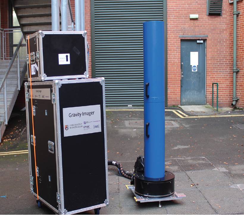
Sensor, developed by the University of Birmingham team, which is aimed at civil engineering applications, performing a measurement.
The inversion in geophysical survey techniques is inherently prone to non-uniqueness phenomena, due to which more than one, and in cases infinite, solutions can exist for one inversion problem.
This is because the inversion of geophysical data is an underdetermined problem due to limited information and a large number of unknowns.
The two main counters to tackle non-uniqueness are improvement of the measurement accuracy and more intelligent inversion algorithms8.
QTGGS are set to revolutionise gravity-based surveys by its unprecedented stability and accuracy, which reduces the non-uniqueness in the inversion of gravity gradient data.
In addition, machine learning-based algorithms that can recognise more realistic solutions and evolve the solutions through an iterative process is shown to be an effective tool.
Among them, genetic algorithm (GA) which is an evolutionary optimisation technique provides a robust algorithm for searching the subsurface using geophysical data 9,10.
To this effect, a machine learning-based inversion tool was developed to infer the acquired data from this new generation of quantum technology-based gravity gradient sensors.
This tool utilises a genetic algorithm to tackle the inherent non-uniqueness of the geophysical problems and produces a density distribution map of the subsurface using the measured gravity data.
The QTGGS and the inversion tool under development by researchers from the UK Quantum Technology Hub Sensors and Timing has the potential to form a powerful survey package revolutionising the field of gravity surveying.
The principles of quantum technology gravity gradient sensing
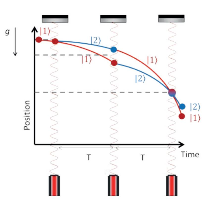
Figure 1: An example of an atom interferometry sequence for gravity sensing. In its most basic implementation, a cloud of atoms initially in their ground state is subjected to a sequence of three laser pulses. The first pulse is used to put the atoms into a 50:50 superposition of the ground |1> and excited states |2>. The atoms, which have absorbed a photon, are put into the excited state and start to move away from those in the ground state due to the transfer of momentum in this process. After a time, T, another laser pulse is applied with 100% probability for the ground state to absorb a photon and 100% probability for the excited state to emit a photon by stimulated emission. Thus, swapping the atoms in the ground-state and excited-state populations. The associated momentum transfer causes the atomic trajectories to converge again after a further time T. The final pulse mixes the populations in both states, creating an interference pattern visible in the populations of the ground and excited states. The interferometer phase is determined by the gravitational acceleration, and can be determined by counting the number of atoms in each state. The gravitational acceleration will vary as the interferometer over areas of low or high density. For example, when the interferometer moves over a tunnel a decrease in the measured gravitational acceleration would be observed.
Quantum technology-based gravity sensors utilise atom interferometry, to perform sensitive measurements of absolute gravity. An example of an atom interferometry sequence used in gravity sensors is shown in Figure 1.
Typically in these sensors a cloud of atoms is generated and are used as a group of test masses. Once generated, the cloud of atoms is typically laser-cooled to a few microkelvins (µK ) above absolute zero, before they are allowed to fall under gravity. As the atoms fall, a laser pulse is used to place the atoms into a quantum superposition, which sends each of the atoms along two simultaneous but different paths in the gravity field.
A second pulse causes the atomic paths to converge again. At which point the atoms are recombined during the final laser pulse. At this point the state of the atoms encodes the value of gravity and can be measured.
To create a quantum technology-based gravity gradiometer two clouds of atoms spaced apart vertically by some distance can be simultaneously used to measure gravity using the atom interferometry technique. By looking at the difference between these two measurements the gravity gradient can be obtained.
If a QTGGS is built in such a way that both atom interferometers use the same laser beam to interrogate the atoms, noise sources common to both atom interferometers are cancelled, including, for example, vibration from microseisms11.
This promises to allow survey times to be reduced as the need to average out noise sources such as vibration are reduced. Research has shown that QTGGS promise a significant increase in sensitivity over existing spring-based classical gravity sensors12.
Additionally QTGGS benefit from a reduced sensitivity to tilt, due to each interferometer having a common and hence cancelled projection of the Earth gravity signal.
These properties of QTGGS are what gives the technology such potential as a survey instrument and will enable deeper and smaller sub-surface features to be detected quicker than is currently possible.
Subsurface feature detection with quantum technology gravity gradient sensors
The University of Birmingham team has developed a quantum technology-based gradiometer, aimed at civil engineering applications, which performs differential measurements on two clouds of 1055 ultracold rubidium atoms, separated vertically by one metre.
Through the system’s novel design and engineering the system remains properly aligned over long periods, making it suitable for field work. The instrument has sensitivity of around 20E (1E is 10–9 per square second) for a measurement taken over 10 minutes, which opens up the possibility to detect a number of subsurface features.
This possibility has recently been demonstrated as part of the Gravity Pioneer project (Innovate UK104613104613) by using the instrument to non-destructively detect a tunnel buried beneath Earth’s surface, located under a road between two multi-storey buildings on the University of Birmingham’s campus13.
The instrument was able to locate the centre of the tunnel to ±0.19 metres horizontally, with a signal-to-noise ratio of eight.
This measurement is the first demonstration of a QTGGS operating outside of the laboratory and helps pave the way towards wider spread use of QTGGS.
Machine Learning for gravity Inversion
In order to provide a complete geophysical survey package, in line with the development of the QT gravity gradiometer sensor at the University of Birmingham, a machine learning-based inversion tool has been developed to utilise gravity gradient measurements for producing density distribution maps of the subsurface and identifying buried anomalies.
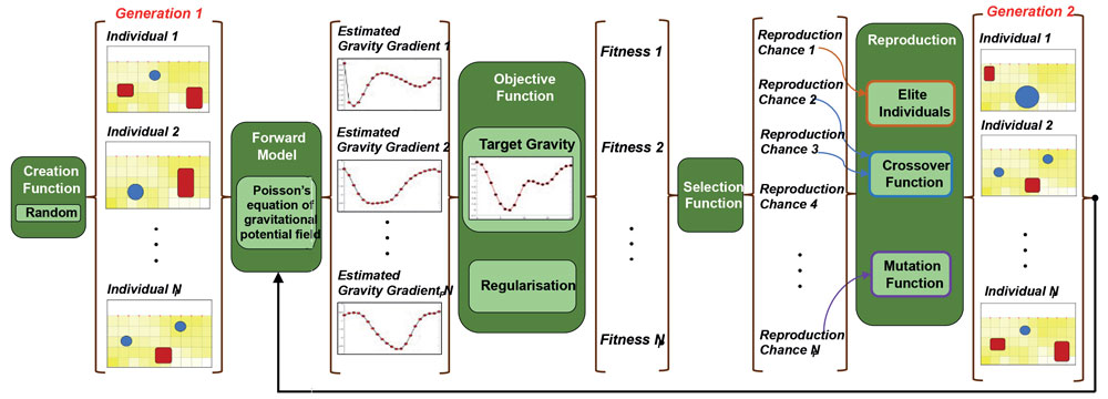
Figure 2: The algorithm of the machine learning-based inversion to infer the location of buried density anomalies from QTGGS measurement data.
The inversion tool incorporates a forward model of the ground and a genetic algorithm into an inversion framework.
The output of this inversion is a density distribution map of the subsurface, from which the location of buried density anomalies is inferred.
The forward model is based on reference14 where the ground is discretised into right rectangular prisms, and each assigned a density value.
Gravity at each data point is equal to the summation of gravity effect over all prisms. In this forward model, gravity gradient is calculated by differentiating the gravity values at two (x, y, z1) and (x, y, z2) points, where z1 and z2 match the height of the interferometers in the QT gravity gradiometer device.
In the inversion framework, the above forward model is optimised by a genetic algorithm (GA) to match the measured gravity gradient data.
Genetic algorithm, inspired by the natural evolution, starts from a set of initial solutions, i.e. first-generation, and improves the estimations using crossover and mutation functions in an iterative procedure. In each iteration, the GA produces a set of estimated density distributions of the ground.
Each set of estimated density distributions are put into the forward model to calculate their pertinent gravity and gravity gradient fields. Then, these gravity gradient fields are compared with the QTGGS measurements. Based on this comparison, the estimations are ranked, and combined to produce a new set of estimations for the ground density distribution that have a smaller misfit between the estimated and measured gravity gradient values.
In addition, a regularisation function was implemented in the GA algorithm to reduce the non-uniqueness of the inversion problem. Nonuniqueness is a common problem in geophysical inversion, where various solutions satisfy the inherently underdetermined geophysical inversion. The regularisation rewards estimations of the density distribution that are minimal with minimum number of density changes throughout the domain, in contrast to scattered variations of density all over the ground domain. This results in more realistic solutions.
Summary and future work
While the quantum sensor demonstrated here, has the performance required to be useful in civil engineering applications, the full potential of the technology has not yet been reached. There is a lot of scope still for improved sensitivity, reduced measurement times and miniaturisation of the sensor, all of which are currently being pursued. For example, the team at the University of Birmingham is currently in the process of developing a downsized version of the gravity sensor used in the tunnel-detecting experiment.
The new sensor is expected to weigh about 15kg, compared with the current sensor used in the tunnel test which weighs around 300kg. Furthermore, the machine learning-based inversion tool is being improved to encompass both more geometrically complex gravity anomalies and higher accuracy measurements of the more advanced QTGGS that are on the way.
The QTGGS and the inversion tool when used together have the potential to offer a reliable tool for inline interpretation of the QTGGS data, a tool for planning the progress of a survey and the ability to produce useful maps of the subsurface.
Farough Rahimzadeh Research Fellow in Geotechnical Engineering, and Jamie Vovrosh Research Fellow in Cold Atom Sensing, Atom Interferometry Research Group, University of Birmingham
Acknowledgments
The atom interferometry team in the School of Physics and Astronomy and the School of Engineering from the University of Birmingham. Plus, support of the Gravity Pioneer consortium, and Matt Stringfellow from RSK Geophysics. This work was supported by the EPSRC through (EP/M013294/1 and EP/T001046/1) and Innovate UK (104613 and 133955(Innovate UK ref: 43439)), and the gradiometer was built under a contract with the Ministry of Defence, as part of the UK National Quantum Technologies Programme.
1 Metje, N and Stringfellow, M, The use of quantum technology gravity sensors in geophysical prospection, Civil Engineering Surveyor, 146, 34-37, (2018).
2 Zouaghi, T ed., Gravity: Geoscience Applications, Industrial Technology and Quantum Aspect, BoD–Books on Demand, 2018.
3 Heimmer, DH, Near-surface, high-resolution geophysical methods for cultural resource management and archaeological investigations, Interagency Archeological Services, Rocky Mountain Regional Office, National Park Service, 1992.
4 Boddice, D, Metje, N and Tuckwell, G, Capability assessment and challenges for quantum technology gravity sensors for near-surface terrestrial geophysical surveying, Journal of Applied Geophysics, 146, 149-159, 2017.
5 Metje, N, Chapman, DN, Rogers, CDF and Bongs, K, Seeing through the ground: the potential of gravity gradient as a complementary technology, Advances in Civil Engineering, 2011.
6 Vovrosh, J and Boddice, D, Towards quantum technology for borehole gravity sensors, Civil Engineering Surveyor, 35-37, 2020.
7 Lines, LR and Newrick, RT, Fundamentals of geophysical interpretation, Society of Exploration Geophysicists, 2004.
8 Parker, RL and Parker, RL, Geophysical inverse theory (Vol. 1), Princeton University Press, 1994.
9 Silva Dias, FJ, Barbosa, VC and Silva, JB, 3D gravity inversion through an adaptive-learning procedure, Geophysics, 74(3), I9-I 21, 2009. 10 Shopova, EG and Vaklieva-Bancheva, NG, BASIC – A genetic algorithm for engineering problems solution, Computers & Chemical Engineering, 30(8), 1293-1309, 2006. 11 Hinton, A, Perea-Ortiz, M, Winch, J, Briggs, J, Freer, S, Moustoukas, D, Powell-Gill, S, Squire, C, Lamb, A, Rammeloo, C and Stray, B, A portable magneto-optical trap with prospects for atom interferometry in civil engineering, Philosophical Transactions of the Royal Society A: Mathematical, Physical and Engineering Sciences, 375(2099), 2017. 12 Boddice, D, Metje, N and Tuckwell, G, Capability assessment and challenges for quantum technology gravity sensors for near-surface terrestrial geophysical surveying, Journal of Applied Geophysics, 146, pp.149-159, 2017.
13 Stray, B, Lamb, A, Kaushik, A, Vovrosh, J, Rodgers, A, Winch, J, Hayati, F, Boddice, D, Stabrawa, A, Niggebaum, A and Langlois, M, Quantum sensing for gravity cartography, Nature, 602(7898), pp.590-594, 2022.
14 Li, X and Chouteau, M, Three-dimensional gravity modeling in all space, Surveys in Geophysics, 19(4), pp.339-368, 1998.