Swing bridge simulation
Lucy Hamilton, KOREC Group
USED to working in microns as millimetres, OR3D is a company that demands high performance for its long and short-range 3D laser scanning operations.
Established in 2011, the business has built its reputation by working on projects as diverse as measuring medication for the pharmaceutical industry through to creating digital twins for some of the UK’s largest infrastructure projects and the reverse engineering of specialist parts for the aeronautical industry through the provision of 3D CAD models from laser scan data.
Whether their clients need a computer model for manufacturing purposes, inspection reports or reverse engineering, the company is equipped to meet challenging and complicated measurement tasks through a portfolio that includes CT scanners, laser trackers, 3D laser scanners and drones.
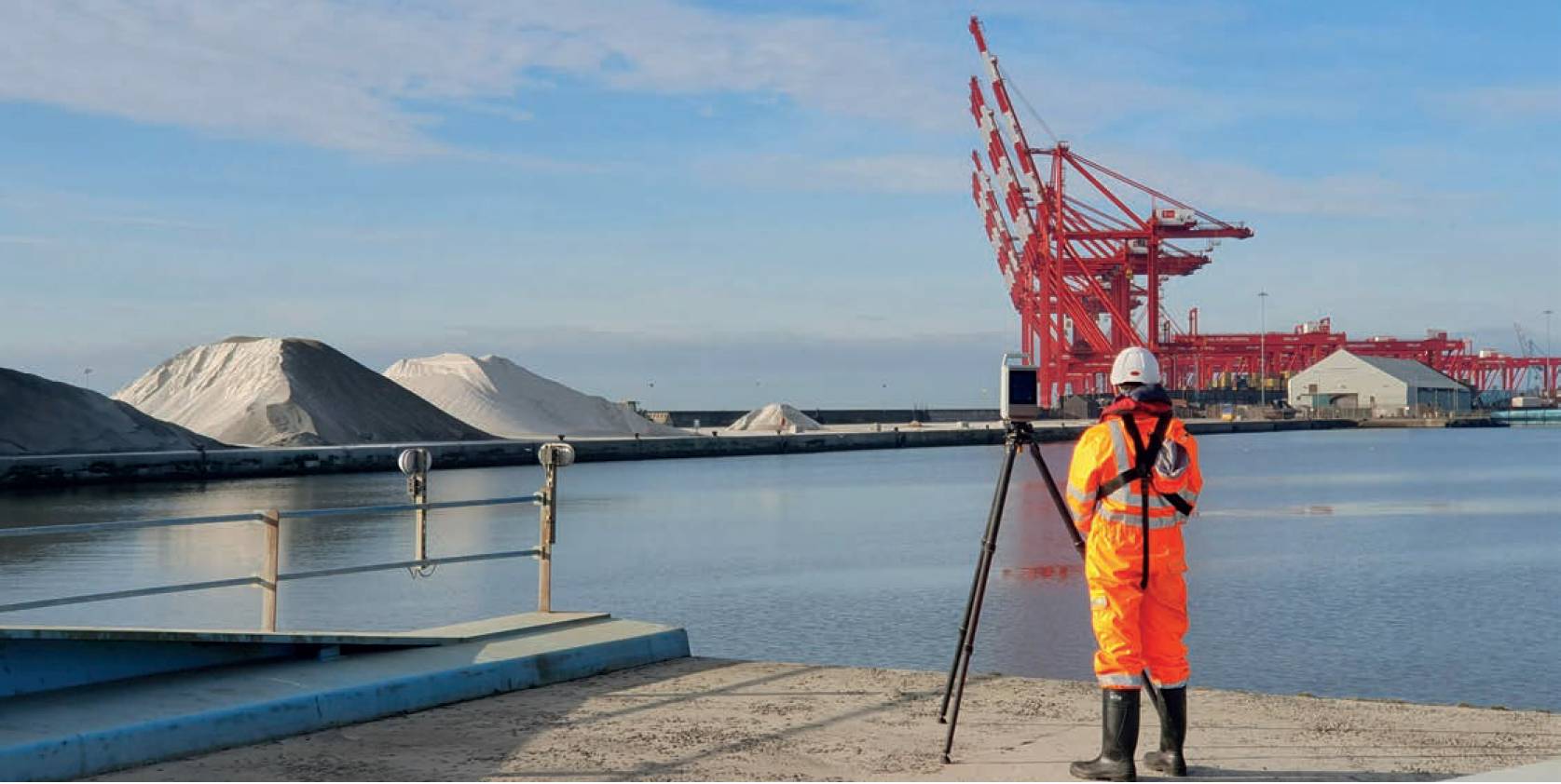
For the reverse engineering side of the business, the introduction of 3D laser scanners has been a game changer. However, as technology evolves, so has OR3D’s investment. This can be seen on a recent project they were involved in to simulate the motion of a damaged swing bridge. Completed for a client in the North West of England, OR3D invested in a KOREC supplied Trimble X12 3D laser scanner to carry out the project.
Swing bridge with a catch-22
Situated in one of the North West of England’s coastal dock systems, the swing bridge connects a section of dock with the mainland. The bridge had been decommissioned and left in the open position following two incidents, including one with a passing tug that had left it twisted. For the ferry company that wished to have access across the bridge for car parking purposes, bringing it back into full operation was vital.
However, this presented a catch-22 situation. The ferry company wouldn’t know if the bridge was functioning correctly unless it closed it, but if it closed the bridge and it wasn’t functioning correctly, it would jam in that position preventing entry by water to the dock.
Digital twin
While the client had previously carried out work for one of the contractors using a laser tracker, which is designed for objects/ short scans, it had also brought the Trimble.
The bridge had been decommissioned and left in the open position following two incidents, including one with a passing tug, that had left it twisted. X7 3D laser scanner to complete scans of the surrounding area. The potential of using a longer-range scanner couple with the client’s expertise would be valuable on the swing bridge project.
Following some initial consultation, it was concluded that a solution for the scheme would include an extensive 3D scan to create a digital twin. The digital twin could then be converted to a 3D CAD model and used in software to simulate the motion of the bridge if it were to be closed.
Capturing the bridge
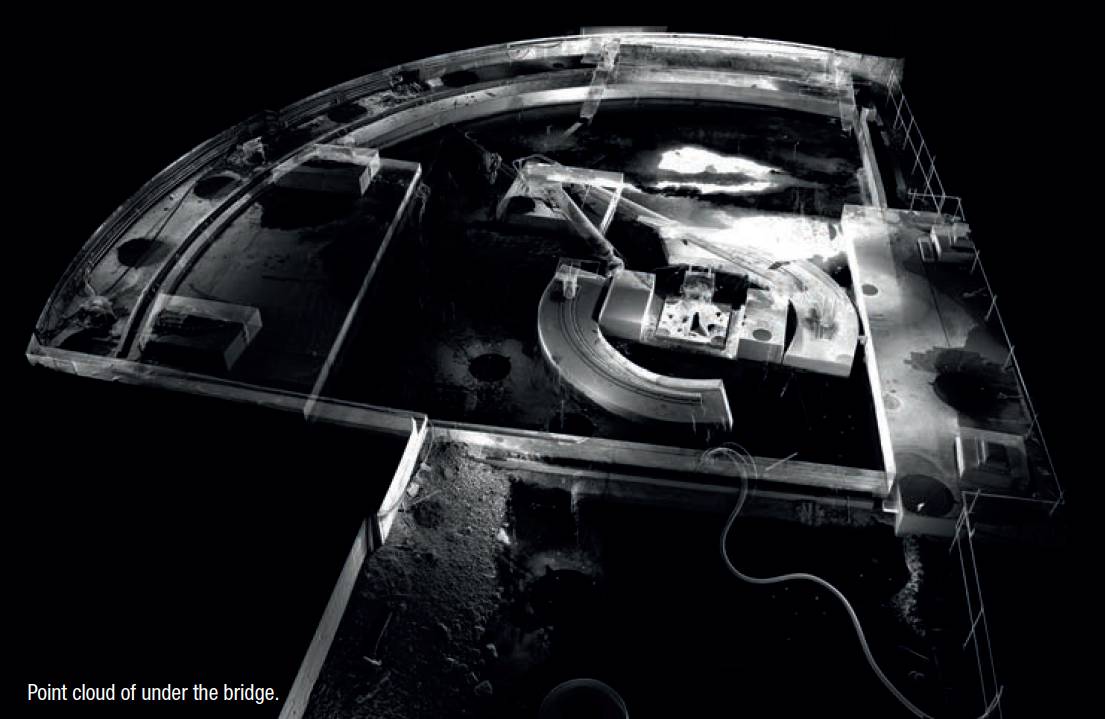
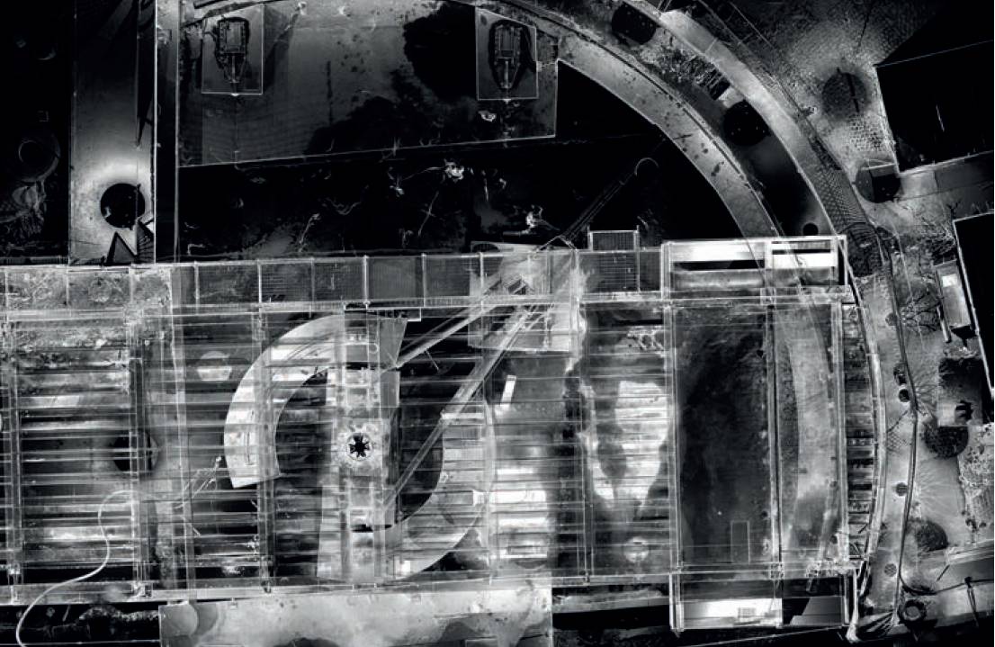
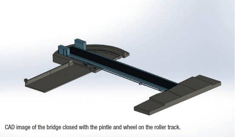
The purpose of the survey was to capture all the intricacies of the bridge, detail all the areas where it might swing, then reverse engineer the bridge to a CAD model and finally virtually swing the bridge to see where it might clash. The pintle/ pivot system included some complicated mechanics and the centre of the pivot point also had to be found. There were also concerns that the bridge had become nonconcentric with the outer roller track and that if it swung, it may fall off the track.
The purpose of the survey was to capture all the intricacies of the bridge, detail all the areas where it might swing, then reverse engineer the bridge to a CAD model and finally virtually swing the bridge to see where it might clash.
Through reverse engineering, although a 3D laser scanner would be the ideal tool for the job, accurate data would also be required. And although the X7 had proved useful, the challenges of the swing bridge project demanded clean data with minimal noise and the ability to scan at both short and long range. Trimble’s X12 scanner was selected after testing the scanner in a number of scenarios, including challenging surfaces such as a black shiny car.
The survey
The project involved delivering data to create a digital twin of the current bridge which would then in turn be used to simulate the expected motion of the bridge.
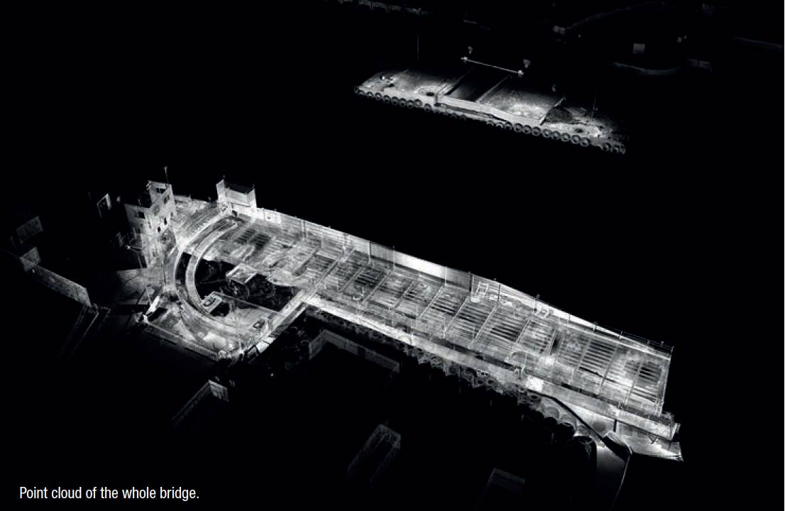
An assessment of the site was made during an initial visit, with the 65m bridge comprising of two sections; one long section going across to the far side of the water and one short, with the pintle at one side of the bridge, going across to the dock. Any inaccuracy would affect where the client extracted the pintle and compromise the height of the roller track.
This could then potentially get projected over the long length of the bridge causing noticeable movement at the nose based on a small amount of error on the short side. Accurate data was therefore imperative.
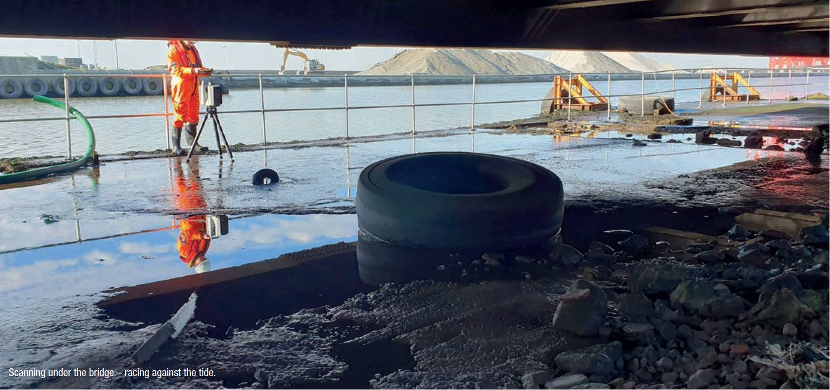
In addition, the bridge was close to the ground so the client needed a scanner with a short standoff to collect data from underneath the bridge without melt-off of the data. The X12 has a minimum range of 0.3m which enabled the client to place the scanner into tight locations and still pick up the clean data needed.
The project involved delivering data to create a digital twin of the current bridge which would then in turn be used to simulate the expected motion of the bridge.
The scanning was carried out with a team of two in a single day shift. 120 HD scans were undertaken along with some window scans, which allow users to select areas requiring much higher resolution data, from each side of the dock to help with registration of the data. With the tide coming in, the team was also aware that time was short – the X12 assisted with this, as did use of the Trimble Perspective workflow from its previous use of the X7.
The software also ensured that the team was able to check the data while still onsite to ensure that no areas had been missed.
Simulation
The data was checked in Trimble RealWorks and uploaded into reverse engineering software, Geomagic Design X. The bridge, the surrounding area and all connecting parts including the pintle and its central location, the roller track and any blocks the bridge sat on in the open position was then able to be modelled. With this exported into software capable of developing 3D models and simulations.
Once constrained, a virtual simulation of the swing of the bridge could be produced to guide whether there would be any concerns if this were to be carried out on site. The software could also generate a list of positions where clashes could occur along with relevant measurements. This information could then be used to adapt the CAD model and rerun the simulation as required.
Lucy Hamilton, KOREC Group